![]()
|
|
Stroud Society of Model Engineers |
The origins of our society go back to April 1972 when after a notice in the local paper 10 people met and decided to form a Society. The first meeting was held on 17th April 1972. Even before the society had a name it was decided to start the search for a suitable site for a railway track. By July 1972 a 3.5" gauge portable track had been purchased with a view to running it at local events to raise money for a permanent track. For the next few years the portable track was used regularly at local events although the amount raised was low. By July 1976 the search for a permanent track site was well under way and by the end of the year a site in Stratford park in Stroud had been offered by the District Council and looked the best prospect so far.
By early 1977 drawings were being prepared for the new track and fund raising avenues were being explored. Planning permission was obtained in Dec 1977 and the following 18 months spent finalising the design and lease from the Council. Permission to start work on site was given in Sept 1979.
By October 1981 the track bed was complete and much of the track laid. At a committee meeting in November it was reported that the 5" gauge track was complete and the points working well. This was just two weeks longer than the planned for date. Much work on the bridges, 3.5" gauge track and super-elevation of the track still had to be done.
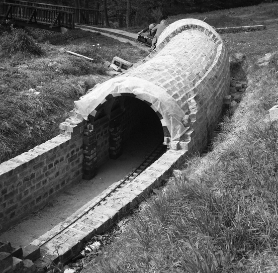
Finishing off took most of the next year but by July 1982 the track was ready for passengers even though there was no station. By the end of 1982 digging the tunnel foundations had been started. By early 1983 the foundations had been laid and the construction of the station was being planned.The station was quickly completed but the tunnel construction had to wait a little longer until the bricks were salvaged and cleaned up. By August the tunnel side walls were up and the arch section started but the arch had to progress in sections waiting for the mortar to harden before the next part was done. By October 1984 the portals were being finished off and topsoil was being readied to cover the top. Bad weather and a number of leaks meant that the tunnel wasn't complete until mid 1985. By this time an extra siding had been constructed by the steaming bays.
During 1986 the idea of a carriage storage shed was being proposed although it was to be several years before a plan was agreed and planning permission requested. By the end of 1990 a start was made and by mid 1992 the structure was complete and in use.
For a history of the park and mansion house have a look at the Museum in the Park web site. Our track is situated in the grounds of the Mansion in part of the area set aside as an arboretum. When first seen there were horses and donkeys grazing on one side of the river and the other side was mature woodland. It must have taken a large leap of faith to work out that a track could be built on site never mind having little money and no vehicle access.
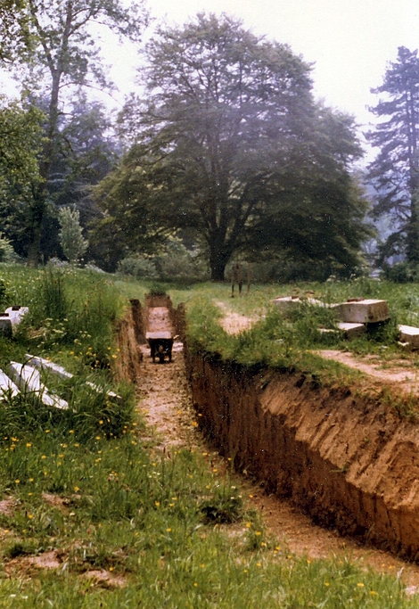
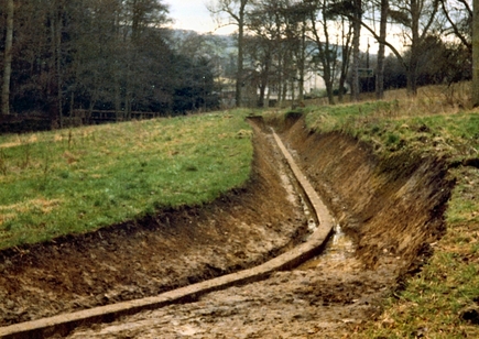
The Painswick brook flows fairly steeply down the valley and at this point there is no flood plain but there is deep clay covering the underlying rock. There is almost no flat land to build a track on so it is laid on bridges, embankments and in cuttings. A very careful survey had been done to work out the track level which gave a relatively flat run and allowed all the material dug out to be used as infill on the embankments.
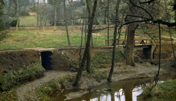
Priority was given to building the bridges to provide access from one bank to the other without a long detour to another bridge in the park. All the materials had to be moved to site by wheelbarrow so every little helped.
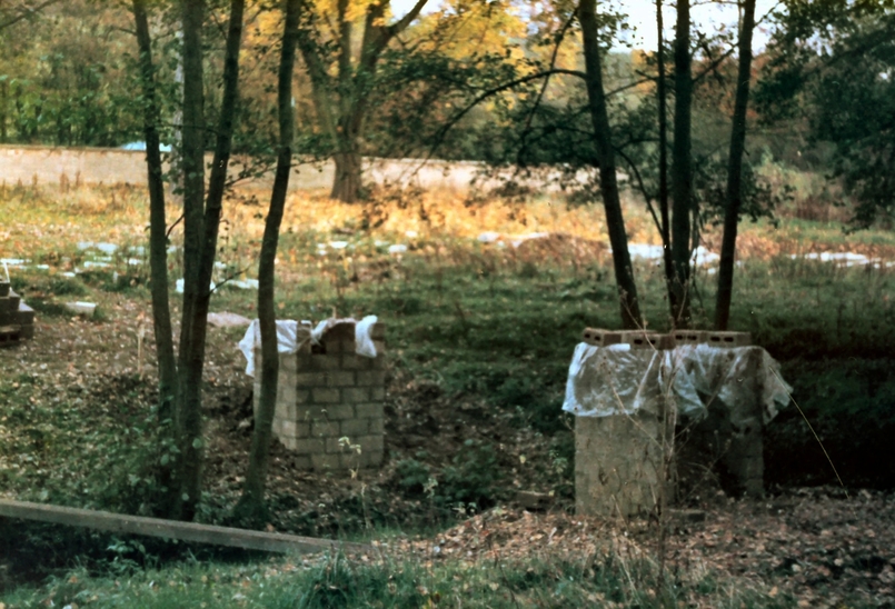
To allow the bridges to be used pillars had to be constructed to support the track coming away from the bridges.
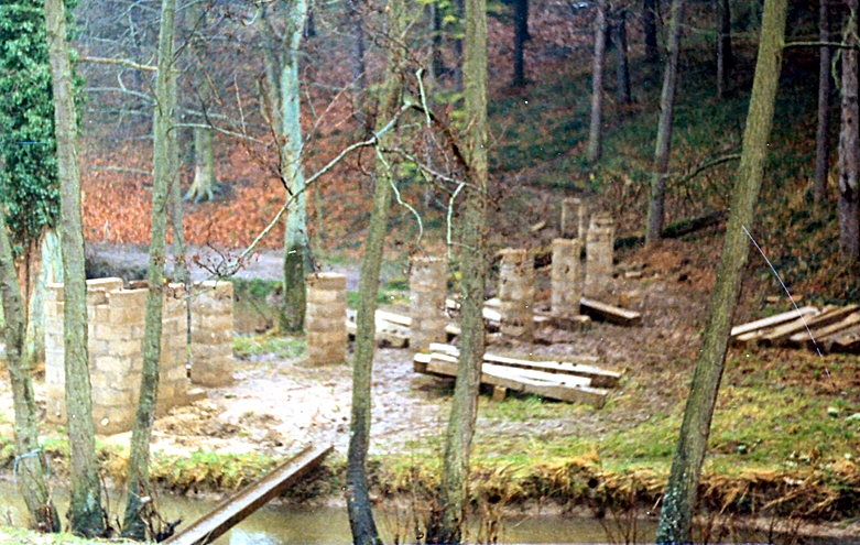
Reject concrete sleepers as used on BR at the time were used as the base for the track. They are laid upside down and go all around the track except across the bridges. They are very heavy and were manhandled using an "A" frame and block and tackle.
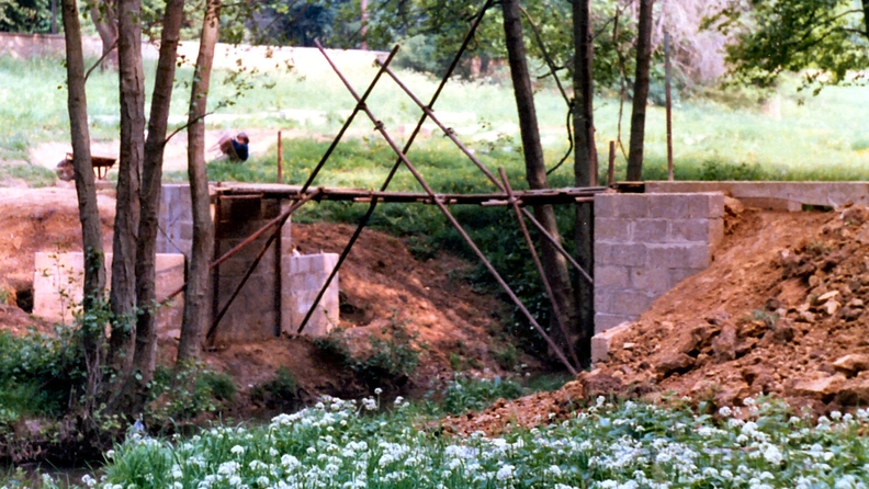
The main source of spoil for the embankments on the west side is from the cutting on the east side so once the wing walls had been constructed the east side embankment was built up and a temporary bridge made from scaffolding poles and planks put across the river. This allowed more spoil to be dropped on the west side.
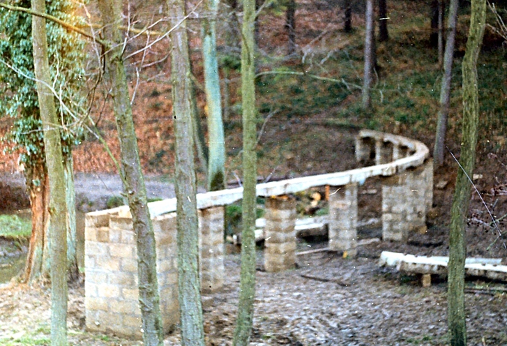
Once the track was complete all round some of the temporary structures could be replaced by permanent structures and a beginning made on landscaping the banks
As soon as the bridges were complete the track panels could be laid and the long awaited first trains run. That wasn't the end of the building though as a tunnel had been planned to add interest to the line.
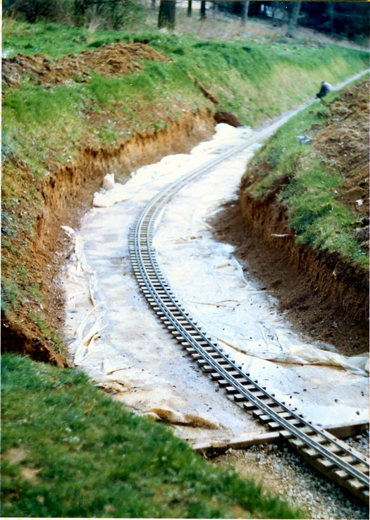
First of all the north end of the cutting was widened and deepened and concrete poured in up to the sleeper level. The question of what type of bricks to make the tunnel out of was solved by a supply of engineering blue bricks being found as the LMS line into Stroud was being dismantled. It meant a lot of cleaning of bricks but the result is a very strong and waterproof tunnel. As the tunnel is on a curve the arch is complex and must have caused many headaches during construction.
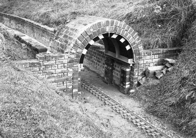
Once the mortar on the first layer of bricks had hardened a second layer could be added a row at a time. During this work the line was kept clear as much as possible to allow trains to run when necessary.
Placing the tunnel on a curve adds excitement for the passengers as they cannot see the exit till they are well through the tunnel. It also adds an element of danger as the driver cannot see what is ahead till they reach the exit. A signalling system is used to ensure two trains do not meet but caution is still required. Ear protection is also sometimes required as some children (and adults) love to scream in the tunnel.